

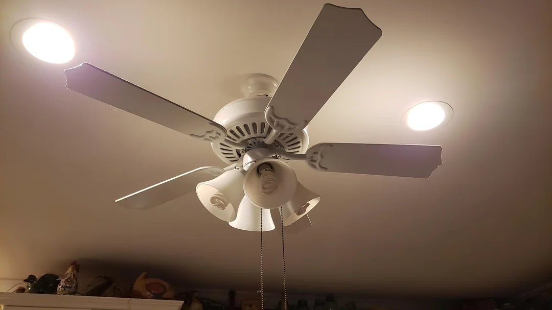

Diagnosing a multi-way ceiling fan switch that no longer modulates fan speeds presents a complex challenge, requiring a methodical approach rooted in fundamental electrical engineering principles and advanced systems diagnostics. This deep dive into troubleshooting methodologies for such integrated electromechanical systems is designed for the seasoned technician or engineer, providing a robust framework for identifying root causes from the line-side power delivery to the load-side motor windings. Understanding the intricate interplay of capacitive reactance, inductive loads, and solid-state switching mechanisms is paramount when confronted with a ceiling fan exhibiting unresponsive speed control, especially in modern installations featuring remote control interfaces and integrated smart home ecosystems prevalent in 2026.
Initial System Diagnostics & Power Verification
Before any intrusive inspection, a comprehensive external diagnostic sweep is imperative. Begin by verifying the integrity of the branch circuit providing power to the fan unit. This involves checking the associated circuit breaker at the electrical service panel; a tripped breaker often indicates an overcurrent event, but a persistently tripped breaker suggests a more serious fault within the circuit or the fan motor itself. Furthermore, assess any upstream GFCI (Ground Fault Circuit Interrupter) or AFCI (Arc Fault Circuit Interrupter) devices that might have been activated, as these are sensitive to ground faults or arcing conditions, respectively, which could manifest as intermittent power delivery to the fan.
Utilizing a true-RMS digital multimeter (DMM), meticulously measure the line voltage at the switch terminals, ensuring it falls within the nominal range of 120V AC (or 240V AC, depending on regional standards). Verify continuity across the circuit breaker poles if it’s in the “ON” position but no voltage is present at the switch. An absence of voltage at the switch, despite a reset breaker, could indicate an open circuit upstream, potentially a loose connection in a junction box or a compromised conductor. Always adhere to strict lockout/tagout (LOTO) procedures before any physical interaction with energized circuits to mitigate electrocution hazards, an indispensable safety protocol for any electrical troubleshooting endeavor.
Dissecting the Multi-Way Switch Mechanism
The “multi-way” aspect of a ceiling fan switch often refers to its capability to select multiple fan speeds, typically achieved through either a rotary mechanism, a pull-chain, or an electronic wall control. Rotary switches commonly employ a series of tapped inductors or capacitors, altering the impedance presented to the fan motor, thereby changing its effective voltage and rotational speed. Wear on the internal contacts of these mechanical switches is a prevalent failure mode; oxidation, pitting, or physical deformation can lead to intermittent connections or complete failure to engage specific speed-control pathways. Disassembly, while often challenging without specialized tools, might reveal visibly compromised contacts requiring meticulous cleaning with a suitable dielectric contact cleaner or, more likely, complete switch replacement.
Electronic wall controls, increasingly common in contemporary installations, utilize solid-state components such as triacs or silicon-controlled rectifiers (SCRs) to chop the AC waveform, effectively varying the root-mean-square (RMS) voltage supplied to the fan motor. These devices are susceptible to transient voltage spikes, thermal fatigue, and component degradation over time, leading to erratic behavior or complete failure to modulate speed. A common diagnostic is to bypass the electronic switch temporarily with a simple toggle switch (ensuring proper load ratings) to ascertain if the fan operates at a single, full speed, thereby isolating the fault to the control module. Always consult the manufacturer’s wiring schematics, as these electronic switches often require a neutral wire connection, which traditional mechanical switches may not, impacting diagnostic pathways for grounded or ungrounded systems in the 2026 electrical landscape.
Fan Motor and Capacitor Integrity Assessment
The operational integrity of the fan motor and its associated run capacitor is critical for speed modulation. Most ceiling fan motors are permanent split capacitor (PSC) induction motors, where the capacitor introduces a phase shift in the auxiliary winding current, creating a rotating magnetic field for starting and continuous operation. Speed control in these motors is often achieved by switching in different capacitor values or by altering the voltage supplied to the motor through tapped windings. A degraded or failed run capacitor will manifest as sluggish starting, reduced torque, or an inability to achieve higher speeds, as the necessary phase shift or effective voltage reduction is compromised. Visual inspection for bulging, leaking dielectric fluid, or burn marks on the capacitor housing can indicate failure, though capacitance measurement with a dedicated LCR meter provides a definitive diagnosis.
Beyond the capacitor, the motor windings themselves must be assessed for continuity and isolation. Using a DMM, measure the resistance across the motor windings (typically start, run, and common). Deviations from the manufacturer’s specified resistance values, or an open circuit, indicate a damaged winding, potentially due to overheating or insulation breakdown. Furthermore, a high-resistance short to ground between any winding and the motor casing suggests insulation failure, which can trip GFCI/AFCI devices and pose a significant safety hazard. While motor winding repair is often impractical for ceiling fans, understanding these diagnostic steps is crucial for confirming a motor-centric failure versus a control-side anomaly, directing the remediation strategy toward either component replacement or a complete fan unit overhaul.
Remote Control and Receiver System Evaluation
Many modern ceiling fans integrate remote control functionality, employing either infrared (IR) or radio frequency (RF) communication protocols to command speed changes, lighting, and other features. When the fan fails to respond to speed commands from the remote, the troubleshooting hierarchy should first address the simplest potential culprits: depleted remote control batteries. A fresh set of alkaline or lithium cells should be installed, followed by a check of the remote’s IR emitter or RF transmitter using a smartphone camera (for IR) or an RF signal detector (for RF, if available), to confirm signal emission upon button press.
If the remote is confirmed functional, attention shifts to the fan’s receiver unit, typically housed within the fan canopy. This receiver is the intermediary between the remote’s commands and the fan motor’s control circuitry. Common failure modes for receivers include fried relays, microcontroller logic board malfunctions, or power supply degradation within the unit. Many receivers feature diagnostic LEDs that can indicate power reception or signal processing status. A direct wire bypass of the receiver (connecting the fan’s motor leads directly to constant power, often bypassing the speed control entirely) can determine if the motor itself is capable of running, thereby isolating the fault to the receiver or the remote system. For RF systems, pairing protocols involving dip switches or specific button press sequences might need to be re-executed, as electromagnetic compatibility (EMC) issues or power cycles can sometimes desynchronize the remote and receiver.
RF Interference Mitigation Strategies
Radio frequency (RF) interference can severely disrupt the communication between a fan’s remote control and its receiver, leading to unresponsive speed changes or erratic operation. Sources of interference are ubiquitous in contemporary environments, ranging from Wi-Fi routers operating on similar frequency bands (e.g., 2.4 GHz), cordless phones, microwave ovens, and even poorly shielded electronic devices. Diagnosing RF interference often involves observing if the fan’s behavior changes when other RF-emitting devices in the vicinity are powered off. Strategic placement of the fan’s receiver unit, away from large metallic objects or other high-frequency electronics, can improve signal reception. For systems utilizing dip switches, experimenting with alternative frequency channels can sometimes resolve persistent interference issues. In extreme cases, specialized RF shielding materials or a move to a different communication protocol (e.g., a wired wall control) might be necessary to ensure reliable operation in a dense RF environment of 2026.
Wiring Harness and Connection Point Scrutiny
The integrity of the entire wiring harness, from the wall switch to the fan motor, is a critical area for detailed inspection. Loose terminal connections, particularly at the switch, within junction boxes, or at the fan’s canopy, can introduce intermittent open circuits, increased resistance, or localized arcing, all of which impede proper power delivery and control signal transmission. Employing a continuity tester or a DMM in resistance mode, systematically check each conductor for unexpected high resistance or open circuits. Pay close attention to wire nuts and quick-connect terminals; these are common points of failure if not properly installed or if subject to mechanical stress over time. Corroded connections, often indicated by green or black discoloration on copper conductors, significantly increase resistance and can lead to localized heating, potentially damaging insulation and exacerbating connection issues.
Furthermore, inspect the condition of the wire insulation for any signs of degradation, such as cracking, brittleness, or abrasions, which could lead to short circuits or ground faults. Ensure that the wire gauge used throughout the installation is appropriate for the fan’s current draw, preventing voltage drop and overheating, especially over longer wire runs. The fan motor leads, particularly those associated with speed control (e.g., separate leads for high, medium, low speeds, or a single lead from an integrated control module), must be meticulously traced back to their connection points at the switch or receiver. A common oversight is a miswired connection where a speed control lead is inadvertently connected to a constant hot lead, bypassing the intended modulation circuit entirely. Referencing the National Electrical Code (NEC) for proper wiring practices is always recommended.
Advanced Troubleshooting: Control Module & Firmware
Contemporary ceiling fans, especially those integrated into smart home ecosystems, often incorporate sophisticated electronic control modules with embedded firmware. When traditional electrical and mechanical diagnostics fail to pinpoint the issue, the focus shifts to these advanced components. A malfunctioning control module, whether due to a failed internal component (e.g., microcontrollers, power regulators, relays) or corrupt firmware, can render the fan’s speed control inoperative. Many smart fans offer a factory reset procedure, which can sometimes resolve software-related glitches by reverting the firmware to its default state. This procedure typically involves a specific power cycle sequence or a button combination on the remote/wall control, which varies by manufacturer and model.
For highly integrated systems, particularly those communicating via home automation protocols (e.g., Zigbee, Z-Wave, Wi-Fi), network connectivity issues or compatibility matrix conflicts can prevent speed commands from reaching the fan. Verify the fan’s connection to the home network and check for any available firmware updates from the manufacturer, as these often address known bugs or enhance compatibility. Diagnostic LEDs on the control module itself can provide crucial insights into its operational status, indicating power, communication, or fault conditions. In some cases, specialized diagnostic tools or software provided by the manufacturer might be necessary for deeper analysis of bus communication or logic gate array states. If all other avenues are exhausted, the control module itself may require replacement, a common repair for sophisticated electronics in 2026 when component-level repair is often cost-prohibitive.
Key Takeaways
- Always initiate troubleshooting with basic power verification at the circuit breaker and switch, employing a DMM for voltage and continuity checks.
- Meticulously inspect mechanical multi-way switches for contact wear, oxidation, or physical damage, which are common failure points.
- Assess the run capacitor for degradation (bulging, leaks) and verify its capacitance, as it’s critical for motor starting and speed control.
- Thoroughly diagnose remote control systems, starting with battery replacement and confirming signal transmission before investigating the fan’s receiver unit.
- Examine all wiring connections for looseness, corrosion, or insulation damage, as these can cause intermittent or complete operational failure.
- For smart fans, consider control module firmware issues, network connectivity problems, and factory resets as advanced troubleshooting steps.
Frequently Asked Questions
Why won’t my ceiling fan change speeds even though it turns on?
This common issue typically points to a failure within the speed control mechanism itself, rather than a complete power loss to the fan. Potential culprits include a faulty run capacitor, worn contacts in a mechanical multi-way switch, a malfunctioning electronic speed control module, or a failed receiver unit if the fan is remote-controlled. The motor might be receiving enough power to operate at a single speed (often high or low), but the components responsible for modulating that power are compromised.
Can a bad capacitor cause a ceiling fan to only run on one speed?
Yes, absolutely. The run capacitor is integral to the proper operation and speed regulation of most ceiling fan motors (PSC type). If the capacitor degrades or fails, it can disrupt the phase shift required for optimal motor torque, leading to sluggish operation, an inability to start, or, critically, an inability to achieve specific speeds, often leaving the fan stuck on a single, usually lower, speed due to insufficient effective voltage or improper winding excitation.
How do I test if my ceiling fan’s remote control receiver is faulty?
To test the receiver, first confirm the remote control itself is functional (new batteries, signal confirmed). Then, carefully access the receiver unit, typically located in the fan canopy. With power off, you can often bypass the receiver by directly connecting the fan motor leads to a known good power source (temporarily, for testing only, and adhering to safety protocols). If the fan motor operates normally when bypassed, the receiver is likely the fault. Some receivers also have diagnostic LEDs indicating power or signal reception status.
Is it possible for RF interference to prevent my fan from changing speeds?
Yes, RF interference is a significant factor, especially in modern homes with numerous wireless devices. If your fan uses an RF remote control, signals from Wi-Fi routers, cordless phones, or even neighboring devices operating on similar frequencies can jam or corrupt the command signals from your remote to the fan’s receiver, preventing speed changes. Troubleshooting involves isolating potential interference sources and, if available, changing the RF channel via dip switches on the receiver and remote.
Should I replace the entire ceiling fan if the speed control fails?
Not necessarily. While a complete fan replacement is an option, often the specific component responsible for speed control (e.g., the multi-way switch, capacitor, or remote receiver) can be individually replaced. Component replacement is typically more cost-effective and environmentally friendly than discarding the entire unit. However, if the motor windings themselves are damaged, or if the fan is very old and parts are scarce, then a full replacement might be the most practical and reliable solution.
Conclusion
Troubleshooting a multi-way ceiling fan switch that fails to change speeds demands a systematic, multi-faceted approach, encompassing electrical diagnostics, mechanical inspection, and, increasingly, electronic systems analysis. From validating line voltage and assessing circuit integrity to meticulously examining the nuances of capacitive reactance in motor operation and the complexities of RF communication in smart fan systems, each stage is critical. Adherence to safety protocols, particularly lockout/tagout procedures, is non-negotiable throughout this process. By methodically eliminating potential failure points, from the simplest battery replacement to the most intricate control module diagnostics, technicians can accurately identify the root cause, restoring optimal functionality to these essential comfort appliances in the contemporary domestic and commercial environments of 2026. This comprehensive methodology ensures efficient and precise problem resolution, minimizing downtime and maximizing operational reliability.